Binary Adder Circuit Diagram

Jose Quigley

Binary adder and subtraction circuits along with its various types Ece logic circuit Adder half circuits subtraction encoding watelectronics
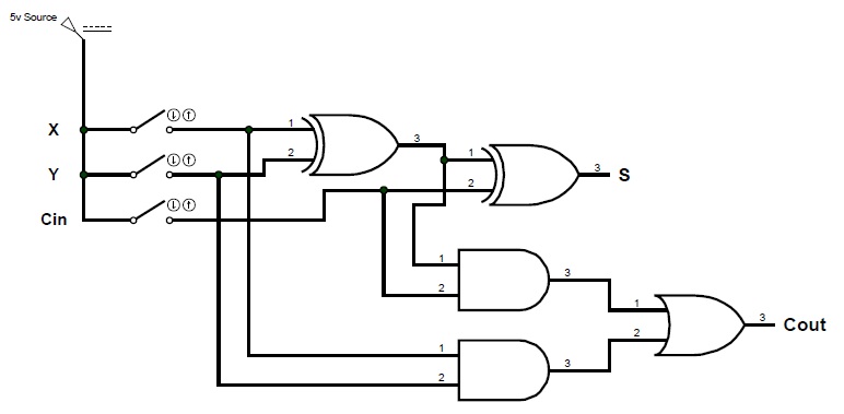
ECE Logic Circuit

ECE Logic Circuit

13+ full adder block diagram Adder diagram binary addition Binary adder and parallel adder

Binary adder and subtraction circuits along with its various types

Adder serial flip flop parallel binary flipflop use clock electronics stack takenTech2play: binary addition Adder binary circuits subtractionFull-adder circuit, the schematic diagram and how it works – deeptronic.

Full adder circuit diagramAdder circuit diagram schematic bit works figure Adder circuit logic subtractor electronics boolean gates outputsAdder cin theorycircuit.

13+ Full Adder Block Diagram | Robhosking Diagram

Circuit adder bit logic ece generate truth table now diagram number

Block diagram of basic full adder circuit .

.

Block Diagram of basic full adder circuit | Download Scientific Diagram

ECE Logic Circuit
ECE Logic Circuit

Full Adder Circuit Diagram

Binary Adder and Subtraction Circuits Along With Its Various Types

tech2play: Binary Addition

Binary Adder and Subtraction Circuits Along With Its Various Types

Binary Adder and Parallel Adder - Electrical Engineering Stack Exchange

Full-Adder Circuit, The Schematic Diagram and How It Works – Deeptronic


YOU MIGHT ALSO LIKE