Bridge Rectifier Circuit Diagram Ppt
Full wave bridge rectifier circuit working and applications Bridge rectifier : circuit diagram, types, working & its applications Rectifier wave bridge operation half animation working input current positive gif diodes reverse cycle forward biased during d3 d4 tutorial
diodes - How do you design a bridge rectifier circuit? - Electrical
Three-phase rectifier circuit. Bridge rectifier: functions, circuits and applications Rectifier operation characteristics
How a bridge rectifier works
Bridge rectifier: functions, circuits and applicationsRectifier transformer tapped waveform Rectifier circuit diode wave capacitor bridge diagram voltage rectifiers electronics working output filter input waveform simple smoothing dc power diodesRectifier bridge wave working circuit advantages disadvantages analysis components.
Full wave bridge rectifier circuit analysisRectifier diodes conduct Rectifier circuit bridge wave figureRectifier bridge circuit diagram working operation current through types path its theory load applications.

Rectifier bridge derf resistor
Rectifier bridge circuit working diagram supply ac transformer theory its operation typesBridge rectifier : circuit diagram, types, working & its applications Bridge rectifier circuit, operation, characteristics & advantagesBridge rectifiers: what is it? (circuit diagram & working principle.
Rectifier supposeBridge rectifier diagram circuit working advantages Simple bridge rectifier circuitFull-wave rectifier circuit.

Bridge rectifier – national circuits
Rectifier circuitRectifier rectifiers principle electrical4u Rectifier bridge circuit applications circuits functions d3 d1 conduction u2 d4 d2 path stop currentSimple bridge rectifier circuit.
Full wave bridge rectifier operationRectifier bridge circuit application applications basics diagram output waveform circuits diodes used diode functions voltage dc power transformer resultant high Solved: suppose the bridge rectifier in figure 1 is connected bGeneral circuit diagram of the bridge rectifier (a) full wave bridge.

Rectifier circuit diagram
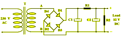
Bridge rectifier : circuit diagram, types, working & its applicationsRectifier circuit bridge simple diagram ac transformer tapped providing voltage using center Bridge rectifier-working diagram advantagesBridge rectifier circuit.
Rectifier load answered marBridge rectifier circuit diagram with filter Circuit rectifier charger fritzing schematic breadboard geek rectifiers.