Buck Boost Circuit Diagram
Buck boost circuit ic using universal output circuits voltage pwm tweet diagram homemade Circuit diagram of buck-boost converter figure 2. equivalent circuit High power inverting buck-boost converter circuit design with tl494 ic
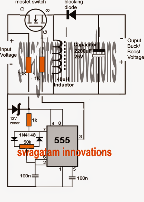
How Buck-Boost Circuits Work - Homemade Circuit Projects
Circuit diagram of buck-boost converter Get torrents from my blog: buck boost converter circuit Buck boost regulator circuit diagram, waveform, modes of operation
Power supply design notes: let's build a bidirectional buck-boost
Buck converter boost inverting circuit ic high tl494 powerBuck boost equivalent Converter circuit waveformsHigh power inverting buck-boost converter circuit design with tl494 ic.
Buck converter boost bidirectional wiring diagram power supply mosfet figure sic notes build letConverter buck circuit boost dc ac diagram converters equivalent working analysis evaluation theory applications equilibrium articles allaboutcircuits four modelling 4a Buck converter boost circuit voltage circuits power dc ac diagram supply gr next torrentsUniversal ic 555 buck-boost circuit.

Buck boost circuit regulator diagram operation modes waveform theory waveforms
Boost buck circuit xl6009 converter diagram regulator using voltage adjustable 12v output 3v switching circuits shown belowBuck boost regulator circuit design using xl6009 with adjustable 3.3v Tl494 buck converter boost circuit diagram power inverting based high ic circuits shown below simpleBuck-boost converter 3-3-1 circuit diagram and key.
Buck boost circuit mosfet diagram state circuits smps exploring concept homemade steady inductor capacitor off work referring aboveConverter evaluation and design How buck-boost circuits work.


